


products categories
Download
 Download file and products catalogue for equipment.
contact us
- If you have questions, please contact us, all questions will be answered
- Tel : 18030236818
- Fax : +86-592 5237901
- Email : dexing@china-dexing.com
hot products
-

DX-100 Hall Effect Measurement System
-
DX-2012HC soft magnetic material coercivity measuring device
-
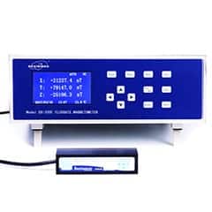
DX-330F 3D Fluxgate Magnetometer
-
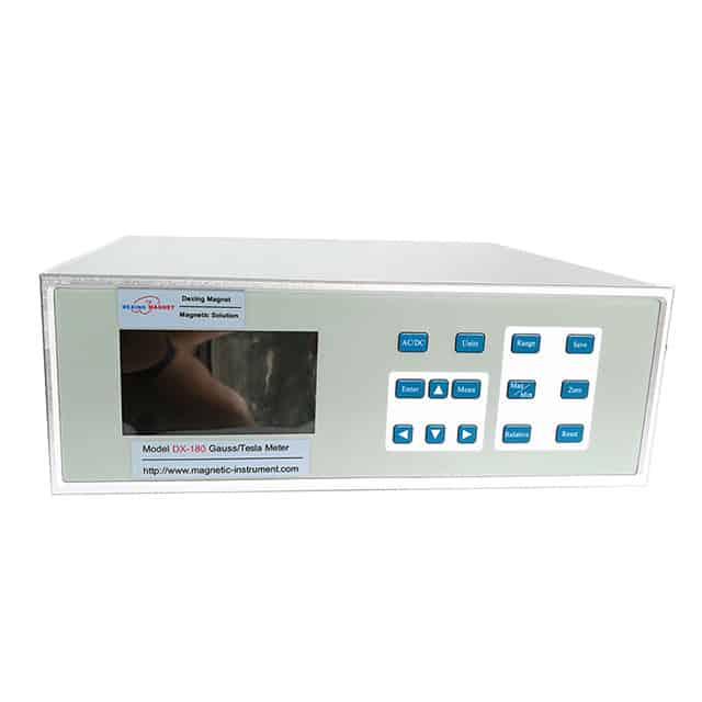
DX-180 Gauss Meter
-
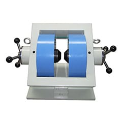
DXSB Double-Yoke Double-Tuning Adjustable Air Gap Electromagnet
-
3 Axis Helmholtz Coils
Hall Effect Measurement System
Principle, test method and application of vibrating sample magnetometer

1. vibrating sample magnetometer Introduction
The vibrating sample magnetometer is suitable for the measurement of various magnetic materials (magnetic powders, superconducting materials, magnetic thin films, anisotropic materials, magnetic recording materials, bulk, single crystal and liquid materials)
2. vibrating sample magnetometer Main use
It is suitable for the measurement of various magnetic materials: magnetic powders, superconducting materials, magnetic thin films, anisotropic materials, magnetic recording materials, bulk, single crystal and liquid materials. It can complete the measurement of hysteresis loop, initial magnetization curve, demagnetization curve, temperature characteristic curve, IRM and DCD curve, and has the characteristics of simple, fast and friendly interface.
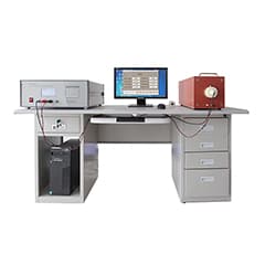
3. vibrating sample magnetometer Structure
The basic vibrating sample magnetometer consists of a magnet and a power supply, a vibrating head and a driving power supply, a detection coil, a lock-in amplifier and a Hall magnetometer for measuring the magnetic field. The vibrating head is used to make the sample vibrate. The instrument adopts the electromagnetic drive method (speaker structure), which is light in structure, easy to change the frequency and amplitude, and convenient for external control. It is connected with the sample rod, and the other coil is connected with a copper block with the same mass as the vibrating rod. The two coils vibrate opposite to each other in the magnetic field, and the phase difference is 180°. In order to stabilize the vibration, amplitude stabilization measures are also taken. On the vibrating rod A permanent magnet is fixed, and the permanent magnet vibrates with the sample. When the vibration amplitude changes, a pair of detection coils placed near the permanent magnet will detect the change and feed it back to the driving power supply. The driving power supply determines the vibration amplitude according to the feedback signal. Make adjustments to make the amplitude stable. Because the vibrating head is a strong signal source, and the frequency is consistent with the detection signal frequency, the probe and the detection coil should be kept at a long distance, the vibration rod should be used to transmit the vibration, and a shielding cover should be added on the vibrating head to prevent Generate induction signal. The vibration frequency should avoid 50Hz and its integer multiples as much as possible to avoid interference. The vibrating head can be rotated at any angle in the horizontal plane to realize the measurement of the sample in different directions. The magnet is an electromagnet, and the diameter of the pole face is 5cm , the pole spacing is 3cm, the maximum magnetic field can reach 1.5T. The electromagnet power supply is a DC steady current power supply, and the maximum output current is 10A. The magnetic field is measured by a Hall magnetometer, which is divided into 4 blocks, the maximum range is 20T, and the minimum resolution The rate was 10-4T and was calibrated by nuclear magnetic resonance method.
4. vibrating sample magnetometer Principle
The VSM measurement adopts the open-circuit method. There is a magnetic charge on the surface of the magnetized sample, and the surface magnetic charge generates a demagnetization field NM in the sample (N is the demagnetization factor, which is related to the specific shape of the sample). Therefore, in the sample, the total magnetic field is not generated by the magnet. The magnetic field H is H, but H-NM. The measured curve needs to be corrected by the demagnetization factor, and H-NM is used instead of H. The position of the sample placement affects the sensitivity of the measurement. The direction of the sample along the line connecting the two coils ( x direction) away from the center position, the induction signal becomes larger; along the other two directions (y and z directions) away from the center position, the induction signal becomes smaller. The center position is the minimum value in the x direction and the maximum value in the y and z directions , is the position where the induction signal is least sensitive to space, called the saddle point. The small area near the saddle point is called the saddle area. When measuring, the sample should be placed in the saddle area, which can minimize the error caused by the finite volume of the sample .
5. vibrating sample magnetometer System functions
The main features of the functional options: Vibrating Sample Magnetometer (VSM) · Fully automatic measurement saves measurement time greatly; VSM high temperature furnace · Small size, can reduce the occupation of laboratory space; Electric transport measurement · No cooling water, high efficiency , low energy consumption; specific heat measurement, no need for liquid helium or liquid nitrogen in the whole experimental process; heat transport measurement, highly integrated, all functions are based on one; and heat transport measurements.